ECT Help ECT Home AP1 Details AP2 Details Buy Here Install Info
![]()

![]()
![]()
![]()
![]()
![]()
![]()
ECT Help
ECT Home
AP1 Details AP2 Details
Buy Here Install
Info
FREE - ECT Module Custom Programming for modified vehicles
Or, forget custom programming by buying our new
ECT-2S with calibrated temperature sensor
|
This is not necessary if you are using the ECT module with a Stock S2000, simply install the ECT module and go. If you are willing to make some voltage and resistance measurements BEFORE ordering your ECT module I can custom-program the module to work in your car. You may decide to do some minor tweaking later, but this process will make sure your ECT module will work reasonably well "out of the box" and will save you lots of time trying to figure out how to get it to work properly. It should take you about 30 minutes to do these tests and there is NO CHARGE for custom programming, so you're silly if you don't do this. After making these measurements email them to me and then order the "Custom Programmed" ECT module from the order page. Buying the Custom ECT does not cost more, it just alerts to me look for your measurement data and program your module before shipping. If you order the "regular" ECT module you will get one off the shelf and it will not have your special programming. Preparation - You will need a decent digital meter for these tests, as you will need to accurately measure voltages less than 1 volt with precision to 1 millivolt (.001 volts). Under the hood, locate your ECT sensor and verify you will be able to get the meter probes into the connector and make contact with the sensor terminals while the cable is plugged into the sensor. You may need to use a paper clip or other thin probe to get a good connection to the sensor wires so get that part set up before starting the tests. Quick Test - Measure the voltage on your ECT sensor when the car is fully warmed up. Connect the meter as shown in step 2 below. If the voltage is between .50 and .60 volts then the "Stock ECM" version of the ECT module will work. If your voltage is outside that range you should complete the tests described below and send me the results. Test Procedure - Do the tests described below and send the results to
|
|
| 1. Make sure the car is completely cold and make note of the ambient temperature. If your car is in a garage that means I need to know the temperature in the garage, not how cold or hot it is outside. We need to be sure the engine (and coolant) has had sufficient time to cool down to ambient, usually overnight is good. (Example of what you'll send me - "Ambient temp 65°F") | |
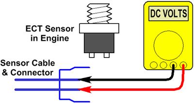
| 2. With a cold engine, turn on the ignition (do not start the engine) and measure the voltage at the ECT sensor. Leave the connector plugged into the sensor and measure the voltage across the 2 sensor wires (black meter lead on one wire and red meter lead on the other). Record this voltage. (Example - 2.615 volts) |
 |
| 3. Disconnect the cable from the ECT sensor and again measure the voltage on the ECT cable wires (not the sensor). Record this voltage. (Example - 5.073 volts) |
 |
|
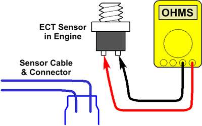
4. With the wire still disconnected from the sensor, measure the resistance (ohms) of the sensor (not the cable). You will need to
measure across both terminals of the sensor. Record this reading in ohms.
(Example - 1328 ohms) If you're not sure how to set your meter, look for a range marked "x1K" or "2K" or "4K". These are typical settings for a meter to measure resistances from 1,000 ohms to 4,000 ohms. Do NOT use a meter range for diodes or for continuity testing (beeper). |
 |
|
5. Plug the sensor cable back into the sensor, attach your
meter leads to the sensor wires, and start the engine. Observe the sensor
voltage and verify that it starts to drop as the engine warms up. Allow
the engine to run until the radiator fan first turns on and record this voltage.
6. Continue watching the voltmeter during a complete "fan cycle" and record the highest and lowest readings. That means you watch the meter until the radiator fan turns off, then continue watching till it turns back on again. During this time, which might be 10 to 15 minutes, keep watching the meter and make note of the lowest and highest voltage readings. (Example - High 0.588 volts, Low 0.492 volts) |
 |
|
Send me an email with the information you recorded from steps 1-6 and then order the "Custom Programmed" ECT module from the order page. It would also be nice if you tell me your vehicle make and model and type of ECM (stock or brand of after-market), maybe even the part number of the ECT sensor on your car. I'll start keeping a database of this information and post it on this web site to help other users. Special Notes 1 - This test ASSUMES your car is operating within it's normal temperature range and is not overheating. If a mechanical problem exists that causes the "fan cycle" to occur at an unusual temperature the meter readings you take will be incorrect. This could be caused by a malfunctioning thermostat, fan switch, or radiator, or if these parts are not the correct ones for your vehicle. If we re-program the ECT module based on incorrect meter readings then your temp gauge will indicate "normal" when the engine is not really in it's normal temperature range. So make sure your engine is operating normally and not overheating when you take these readings. 2 - Pay close attention to the voltage as the radiator fan turns on and off. You should NEVER see the voltage change suddenly; it should always be a smooth gradual change. If the voltage jumps when the radiator fan turns on or off, or if it changes when you turn other accessories on or off (headlights, air conditioner), then you have a ground loop problem that must be fixed before using the ECT module. See here for more information. |
|
Copyright 2005 by Modifry
Products, LLC all rights reserved.
Modifry and the "squiggly arrows" design are trademarks of Modifry Products,
LLC.
AEM and AEM EMS are trademarks of AEM Performance Electronics.
Neither Modifry Products, LLC
nor Modifry.com are sponsored, endorsed, affiliated or authorized by AEM.